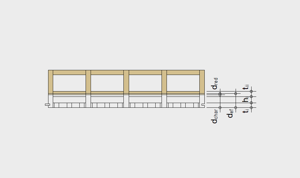
Residual section after fire load
All the following information and calculations are based on the assumptions stated here:
- one dimensional charring
- charring rate β1 at the layers = 0.8 mm/min
- charring rate β2 at the webs around the insulation
- layer accounting for loss of strength dred = 7 mm
β1 = 1.6 mm/min for rockwool
β2 = 0.9 ⋅ √ (450/ρIso) mm/min for wood fibre
ρIso = density of wood fibre

Effective combustion depth surface element
def = dchar + dred
def = 31 mm für REI30 = 30 min ⋅ 0.8 mm/Min + 7 mm
def = 55 mm für REI60 = 60 min ⋅ 0.8 mm/Min + 7 mm
def = 79 mm für REI90 = 90min ⋅ 0.8 mm/Min + 7 mm

Effective combustion depth Surface element insulated
def = dchar + dred
Example :
ti = 40 mm, mineral fibre (A2-s1, d0 and melting point ≥ 1000°C)
def = 63 mm for REI60
= 50 Min ⋅ 0.8 mm/Min + 10 min ⋅ 3.0 mm/Min + 7 mm

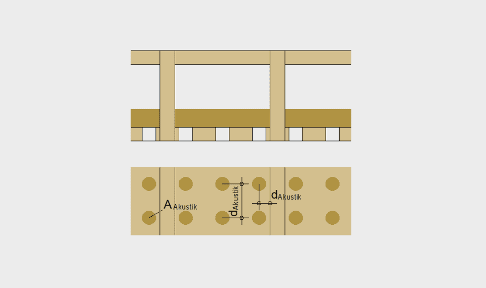
Residual section of acoustic element after fire load
The charring rate β0 of the acoustic slat can be described based on the following parameters:
AAkustik (mm2) = perforation area
dAkustik (mm) = perforation area
bAkustik (mm) = position of perforation in relation to the timber web
ti (mm) = thickness of the acoustic slat
The factor k summarises the resulting influence of the parameters. The charring rate β1 can be calculated depending on the factor k.
k = AAkustik / dAkustik . 103 / (bAkustik 1.5 . ti)
β1 = 0.22 ⋅ k + 0.72
The charring rate β2 at the webs around the wood fibre absorber depends on the density ρAbsorber (kg/m3).
β2 = 0.9 . √(450 / ρAbsorber)
Effective combustion depth: example acoustic type 2, REI30
def = dchar + dred
Example akustic 2:
- ti = 31 mm, hi = 40 mm, ρAbsorber = 110 kg/m3
- AAkustik = 707 mm2, dAkustik = 75 mm, bAkustik = 25 mm
- => k = 2.43, β1 = 0.22 ⋅ k + 0.72 = 1.26 mm/min
def = 48 mm für REI30
= 24 Min ⋅ 1.26 mm/Min + 6 Min ⋅ 1.82 mm/Min + 7 mm

Effective combustion depth: example acoustic type 2, REI60
def = dchar + dred
Example akustic type 2:
- ti = 31 mm, hi = 40 mm, ρAbsorber = 110 kg/m3
- AAkustik = 707 mm2, dAkustik = 75 mm, bAkustik = 25 mm
- => k = 2.43, β1 = 0.22 ⋅ k + 0.72 = 1.26 mm/Min
def = 89 mm für REI60 =
24 min ⋅ 1.26 mm/Min + 22 Min ⋅ 1.82 mm/Min + 14 Min ⋅ 0.8 mm/Min + 7 mm
Joint detail under fire load
Basic boundary conditions for space-enclosing and heat insulation effects must be met in the event of fire. LIGNATUR floors and roofs with fire resistance class REI30, REI60 and REI90 have to be installed according to ETA-11 / 0137 with the appropriate joints, shown on the right. They already reach EI30, EI60 or EI90, so that floor and roof structures can be chosen freely without further requirements.
